HQ-180: A Big Noise Problem Means Drain the Swamp
By Tom Taylor
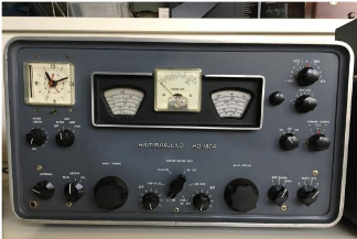
About the time of the Chevrolet 409/427 engine, when the Shiffons and the Beach Boys played on your car dial and NASA’s Mercury program enthralled the public, there was an 18 tube receiver by Hammarlund known as the HQ-180 which could be bought for $443 less tax or shipping. Does someone know what a Chevrolet Impala cost at that time; around $2000. While not the Mil Spec pedigree, this receiver can still command $300+ in good condition and 5/5 reviews by its users. At 45 pounds, it’s a true boat anchor; but with triple conversion general coverage circuitry, it is considered a SWL or classic radio contest contender worth capture. Receiving a sick one for repair does not by itself cause fear, but that can change when full restoration of sound brings troubled audio swamped by heavy static. The static that reminds you of a bad IF can. Suddenly the associated parts count and those 40 or so adjustments lined up inside can bring on anxiety in the heart of any technician. For the purpose of explanation and hopefully as some guideposts for other restorers, a summary of ills found during a recent HQ-180 confrontation is provided here.
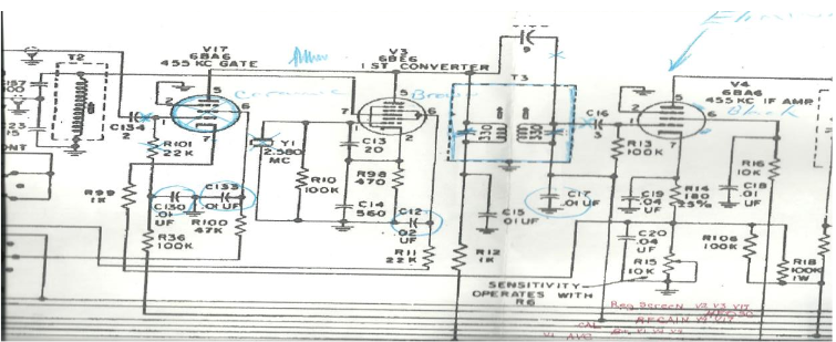
This HQ-180’s voice was somewhat restored with the removal of one shorted and two weak tubes. This however unveiled a good deal of audible noise from the speaker where signals should have been found. For some reason that noise became so dominate during troubleshooting that all but the strongest BCB stations were being overwhelmed. To locate the source of noise, tubes were pulled and replaced one at a time on the way from the last detector (the one driving an audio string) back towards the RF stages until the noise could no longer be interrupted. My new home for the next few months was therefore around the first detector (AKA mixer). (See schematic below.) These delays were driven by far easier radio requests, house and truck needs and I admit it, fear.
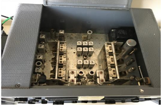
Since the noise source was just ahead of the last removed tube, attention turned to everything after the first mixer V3 and specifically around V17, a 6BA6 gate to enable the 455 KHz IF string as a part of one of the three conversions. After systematically lifting one end of parts in the area to find them good and probing tube socket pins with and without the tube in place, the scope displayed all manner of signal twitching going on at its screen grid pin while the tube lay nearby on the bench. When both R and C at that point where found good I stared at a tube socket buried in space critical point to point miniature tube socket layout and reluctantly decided to change it out for an exact replacement NOS ceramic rescued from antique stock. However, I should have looked close at it, or found an ultrasound cleaner or even considered some manner of socket preparation because I had a similar outcome once that socket was installed. After reluctantly performing the same diagnostics as before, I concluded the replacement socket was also troubled: lightning strikes twice in radio repair. A NEW Chinese ceramic socket was then provided by a club member and that problem was at last history. Keep in mind that when so many amplifier stages follow a problem area, it doesn’t take much of an issue to become real big at the speaker. For that reason the scope gain had to be near max when the screen grid condition showed itself.
Draining the swamp, however, had now allowed me to hear BCB stations and more clearly a second contributor of noise as well as a peculiar distortion on SSB when moving the front panel switch from USB to LSB. Lifting and measuring components and then isolating inputs to the next area just downstream brought attentions to an IF can T3 with no less than 9 leads tied to it.
Following a few episodes of double checking and days of hesitation I decided to perform an “IFcanectomy” knowing full well that there were about 27 other cans just like it in this 6 band triple conversion circuit. Sure enough, both capacitor insulators in this can had metal deposition with nearly 60% coverage. Those insulators were removed, mounted in glass and shown about during one of our general meetings. The can was then reassembled, remounted and external caps of the same value as those removed were installed across both windings along with the original 9 leads.
Alignment of the can and those remaining in the 455 string brought up signals without noise but with the suspicion that someone had tried alignment of that area. Faced with that condition, the lack of gain and the sound fidelity suggesting bandwidth shifting, I had to align the right side of that radio involving most of those IF cans serving all 3 IF frequencies one of which was 60KHz. Have you a 60KHz generator you consider stable enough to do that task? That is not 600KHz you read. My Wavetek model 164 was in no way stable enough for the task nor was a Tenma toy model 72-7210 while the 8 tube URM-25D was an absolute rock on that frequency as long as you had power for it. Oh, and that SSB distortion was caused by a bad 6BV8 that had passed an earlier Hickock 600 test which included leakage checks. You find those escapees in desperation during a one for one replacement. Suspicions about AM audio quality was further dispatched by replacing the audio stage encapsulated circuit with its discrete component counterparts and a most suspicious looking cathode bypass electrolytic. As Columbo says, “one more thing”. That Slot Frequency control for signal notching in the upper right of the front panel was put on target with an adjustment of L3.
Although the end result appeared to measure up to written claims for this radio, I for one would hesitate to buy one of these fine receivers if its sound brought back memories. The owner of this set however was extremely happy to start hearing the radio perform closer to potential. He said he ogled one of these for years while a teenager but never could afford that $400+ price tag back in the day. The figure included here shows the circuit area that got so much attention