THE REFLEX RADIO
by Ron Soyland
Back in the 1920’s tubes were expensive, usually the most expensive part of a radio. So experimenters wondered if there was a way to make use of a single tube to amplify both the RF signal and then the AF signal, thus getting double use from the tube. This was deemed possible because of the large separation in frequency range of the input RF and the output AF signals. They should not interfere with each other. This worked very well!
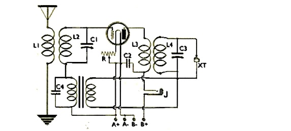
Examine the circuit. The input from the antenna and ground is to the input transformer, which is a RF type. Some people used a loose coupler. The secondary L2 was chosen to resonate at the desired frequency range with tuning condenser C1.
The tuned circuit was connected directly to the grid without grid leak bias so the tube would amplify RF signals.
The plate transformer is also a RF type. The primary L3 was made to have about 1000 ohms reactance at the lowest frequency to be tuned. The secondary L4 was made to tune the same range as the input transformer via condenser C3.
The secondary circuit is connected to a crystal detector XT. The circuit must use a separate detector because the tube must operate linearly to amplify the audio signal without distortion. (Using the tube as a detector biases it non-linear so it would severely distort the sound if this were attempted.)
The crystal detector audio is connected to an audio transformer. The ratio of this transformer determines the ultimate gain of the circuit. A 1:5 or a 1:10 transformer gives the best gain. The low impedance side is to the detector. The condenser C4 bypasses the high RF reactance of the audio transformer winding for the RF signals on the input circuit. This condenser is a small value such as 200 pf, which has low shunting effect for the audio and yet passes the RF signals to complete the input circuit.
The AF signal from the transformer secondary connects to the grid through RF winding L2. This winding has low reactance at AF so no signal loss is present. The amplified audio signal from the plate passes easily through the RF transformer primary to the headphones which plug into jack J. Condenser C2 provides a low impedance path for the RF signals and is picked to have no shunting effect on the AF signals. A value of 500 pf is typical.
By tuning the plate circuit via condenser C3 the phase of the RF signal in the primary of the transformer can be made to be in phase with the signal input. This results in regeneration, where some of the output signal is fed back to the input through tube inter-electrode capacitance. The careful adjustment of the tuning can result in substantial regenerative gain, resulting in performance of this circuit easily hundreds of times that of a simple grid leak detector circuit using the same components!
The connection of the audio back through the tube is why the circuit is called reflex.
To illustrate one approach we first chose to reason what was needed in that circuit and make a corrective resistor choice that approximated the need. Using the base diagram from a tube manual and examining the radio wiring we saw the suspect replacement resistor was tied between the plate of a 12SQ7 triode and the B+. It’s a plate load resistor where signal voltage is developed. The suspect replacement was approximately 270 ohms which for all the world had to be wrong since the tube manual says the triode portion of that tube is only capable of 1 ma plate current. With that value the maximum signal voltage available across THAT plate load value was a wimpy 0.001 X 270 = 0.27 volts. Clearly the selection of a much larger plate load resistor there would significantly increase the signal voltage available to the following 50L6 control grid. The highest resistor we had on hand was a 22K ohm and once it was installed we had our confirmation with plenty of volume to the speaker. Since this volume did not confirm a good final choice, a look into other schematics was undertaken where we turned up use of a 12SQ7 AND the observation that a 470K ohm resistor was much more fitting.