The Junk Box Preamplifier
by Bill Werzner
A couple of months ago one of our customers at Vintage Sounds was in need of a not too expensive pre amplifier that could amplify sound from two of his older model turntables to be fed into an older amplifier. The problem being, was that the output from his record players was not strong enough to produce a signal for sufficient volume. This was a problem that I had toyed with in my mind for several years. In our business we deal with vintage equipment and I could foresee a problem like this at some point in time. The homebrew preamp he brought in for repair, and I won’t go into details, was beyond repair. So, I decided to experiment starting with a schematic I found while surfing around on GOOGLE one evening.
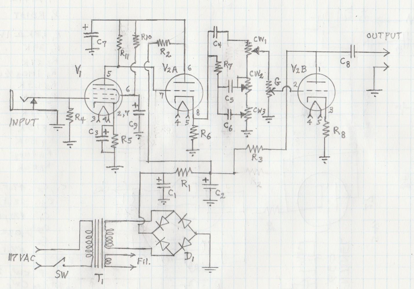
Schematic for a Junk Box Preamp by Bill Werzner, Vintage Sounds, Houston, Texas

PARTS
C1, C2, C7 47 uF 250 V. electrolytic D Full wave diode RB 157 R9,R11 150 K Ohm 0.5 Watt
C3 22 uF 50 V. electrolytic G 1 Meg. Pot. / switch SW T1 Power transformer P-T442
C4 470 pF 200 V. ceramic R1 1.8 K Ohm 1 Watt 117 V. pri. 12.6 V. & 117 V. sec.
C5, C6 0.022 uF 200 V. ceramic R2 39 K Ohm 0.5 Watt Antique Electronic Supply
C8 0.10 uF 250 V. polypropylene R3 27 K Ohm 0.5 Watt Tempe, AZ
C9 1.0 uF 250 V. electrolytic R4,R10 1.0 Meg. 0.5 Watt V1 12AU6, V2 12AU7 tube
CW1 250 K potentiometer R5, R8 1.5 K Ohm 0.5 Watt Note, 6AU6 tube used if T1 has
CW2 1.0 Meg. potentiometer R6 47 K Ohm 0.5 Watt a 6.3 V. fil. Supply & use 12AU7
CW3 25 K potentiometer R7 33 K Ohm 0.5 Watt pin #9 fil. tap for 6 volt supply.
Voltages: B+ at: C2 150.5 V., V1 plate 93 V., V1 (pin 6) 27 V., V2A plate 140 V., V2B plate 84 V.
The author of the article described the preamp as a knockoff version from a Marshall amplifier. With an inexpensive small power transformer, two common tubes and a hand full of common components, this was the chance I had been waiting for. I built this unit on an aluminum bud box one evening at my work bench. Notice how the input signal is fed directly to the grid of the 12AU6 tube. CW1 adjusts treble, CW2 bass, and CW3 is for mid range. When I fired it up with headphones connected to the output, I was amazed at how well it performed when I fed a really weak audio signal into it from a bench radio – I think you will be too. The author of the original design coupled a 22 uF cathode bypass capacitor in parallel with R8, but removed it as the output was too loud! Be careful when you hook this one up – you might blow a speaker cone or knock your neighbors out of bed.