Understanding Negative Bias
by Tom Taylor
Let’s talk negative for a moment and for clarity the topic is about radios with power transformers. I for one hesitate once in a while when looking at a schematic while trying to sort out how and why a negative voltage is generated in the circuit. Take a look at the tube manual for audio output tubes like the 6F6, 6K6, 6V6, 6L6 or 6550 and you see that there is a NEGATIVE voltage required for their bias. By the way, each of those tubes use essentially the same base diagram and a very similar negative bias. That bias is a voltage on the control grid relative to the cathode, not relative to ground. Knowing this is even more important when there is a cathode resistor to provide what is called self-bias. If that control grid voltage gets more positive than the recommended negative voltage the tube starts conducting more and you might think of this condition as an isometric exercise that gets progressively more strenuous. The tube simply starts heating up a bit more with no signal or amplification benefit. Ideally we want a single ended audio output tube like the 6L6 to have its plate current rest point in the center of its range of capability so that it or the plate voltage can swing equally in the positive or negative direction. It is at that point we will find the least distortion or compromise to the positive and negative swings of its signal output voltage found on the plate. For a circuit using a push pull pair of 6L6s we instead provide a different more negative bias that turns each tube ALMOST OFF to insure each is idling but ready to swing in its respective direction without hesitation. We might then consider both tubes up on their feet linked with rope and ready to run, each in separate directions.

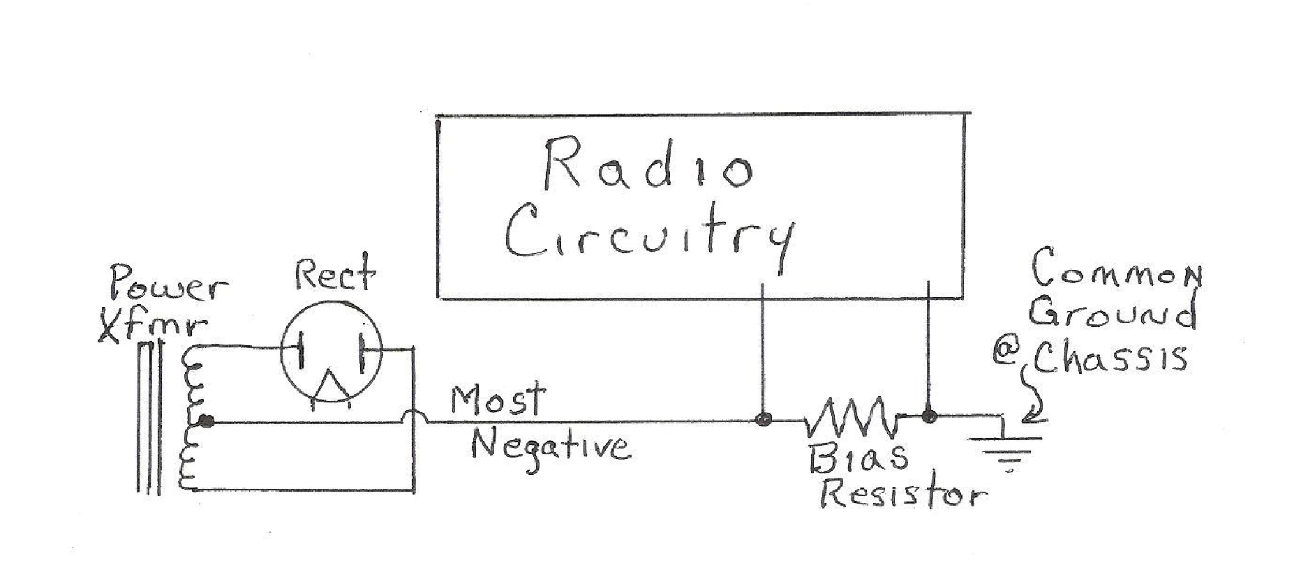
The negative voltage used as a bias in radios with these and other similar tubes is found with respect to ground, most often chassis ground. Production of a negative bias voltage with respect to ground might be considered a clever trick performed by HOW we connect our most negative power supply wire. The most negative voltage found in the output of a full wave rectified power supply is at the center tap of that high voltage transformer secondary OR if a solid state bridge rectifier is used, at the junction of two diode anodes most often labeled with a ‘-‘ negative sign. IF we first connect that negative supply output to a small value resistor say 220 ohms and then tie the other end of that resistor to chassis ground where return current from the positive supply output and radio circuitry is arriving we find that the chassis voltage is higher on chassis ground with respect to the supply negative output. Saying that the other way, the negative power supply output is now more negative than the chassis ground. Designers simply derive the negative bias voltage they want by changing that small value resistor UNTIL they arrive at what the tube manual or tube performance curves indicate for the supply voltage in use. Keep in mind that with rare exception all other circuit grounds are elevated grounds such as on the chassis and only negative bias voltages which are generally for audio outputs come off that resistor trick on the power supply negative return line. Ever put a supply filter electrolytic in backwards to get a dramatic notice of what you did? Well, you have to pay even more attention when installing an electrolytic across a negative voltage source.