Farm Set Antenna Coil Problem & 3 Coils in the Drawer
by Bill Werzner
Have you ever had one of those restoration projects that despite having changed out all the old defective and out of spec components, the radio reception still sounds “anemic” for better description? I had one of those on my bench a couple of months ago. It was a beautifully refinished wood cabinet farm radio that had a nostalgic value attached to it by the owner. A replacement dial lens had to be ordered as the original was in pieces. Every component had to be replaced under the chassis along with an i.f. transformer, and two tubes. I had a Sears generic farm set power supply in my surplus bin, you know the black metal box type with multiple sockets along the side, but like the radio it too had to be refurbished. The old selenium rectifiers inside were shot as were the original 70 plus year old filter capacitors. The radio was probably stored in a barn or shed for quite a few decades before someone recognized it as great grandpa’s prized Sears model 101.642 radio from 1941 and decided to get it restored to its original beauty. Yes, the cost for parts and labor ran high and I was proud of how it looked after the chassis was cleaned and the radio actually played for the first time in many years. Despite two alignments, the reception was far below expectations. I finally concluded that something in the antenna circuit was causing the problem. Looking over the antenna coil circuit in the schematic (see fig. 1) brought back memories of an almost identical circuit in a Majestic model of the same era that had the same problem. What was good for that Majestic, might work here too. That was when I decided to perform MAJOR SURGERY. Most antenna coil circuits are pretty simple, but if the guy designed this one and the one in the earlier Majestic, well he must have had his head up where the sun don’t shine! If he was a cab driver he would have taken me from Houston to Dallas via New Orleans! Why make a simple circuit so complex?

fig.1 Schematic shows the Sears Model 101.642 farm radio. Note antenna circuit in upper left.
In the excision, everything to the left of capacitor VC and the 2.2 Meg. resistor were removed.
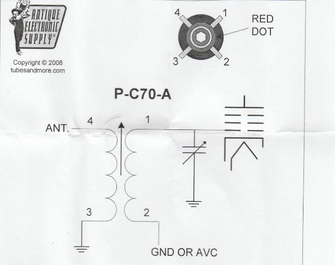
A universal replacement antenna coil cat. item P-C70-A from Antique Electronic Supply was then installed after a hole was drilled in the chassis for its mounting. (See fig. 2) below.

Fig. 2 Universal antenna coil installed. Note switch lugs were combined and soldered to lug #1 on the P-70-A
The ferrite coil was adjusted after the antenna wire was connected to my aluminum gutters and the reception and sound volume must have increased over 75%! Wow, I could not believe what an improvement that coil made. Yes, that is a coil to have on hand if you are in to repairs and restorations.
Now for Three Coils in the Drawer. Antique Electronic supply sell three universal coils that I would not be without. First is their Universal Oscillator Coil, cat. Item P-C70-OSC. That coil is the one I have used most of all. It can be wired into three different configurations shown below and has always worked extremely well. It is the same coil that AES use in their AM transmitter kit. Can you identify the Hartley example?

 The second most used coil is the Universal
Antenna Coil I described it in the above Trouble Shooter article; the P-C70-A Antenna
Coil.
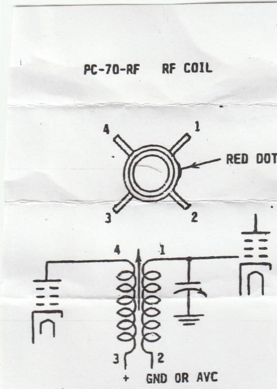
 Third is the RF coil that you will want to stock especially if you work on very old sets requiring missing or defective interstage transformers. Like the two previous coils, it too is slug tuned and may require a hole be drilled in the chassis for mounting.
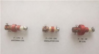
 All three coils are shown here, from left to right:
P-C70-A Antenna Coil